Machine Setup MISC Parameters
****Basic Machine Info****
Machine Type: Type in ML18, etc.
Machine Version: The current model
Mechanical Version The current mechanical version
Electrical version The current electrical version
Machine serial number The machine serial number
Slow Rapid Percent Sets the percent of rapid when the leftmost of the three front panel
Rapid keys is active Generally set to 10, matching the 10% embossed on the key.
Check Spindle Up to Speed
“Off” - The control never waits for a spindle up to speed signal.
“On (M3⁄M4)” - The control will wait for up-to-speed signal from the spindle controller after
an M3 or M4 command.
“From Rapids to Feeds” - The control will wait for an up-to-speed signal from the spindle
controller before continuing to a G1, G2, or G3 block from a G0 block.
Up to Speed Input #: Specifies the input for the up to speed signal.
Spindle Encoder PPU: Pulses per rev of spindle, used for hard tapping option and displaying
the RPM.
Handwheel Encoder PPU: Pulses per rev of the handwheel, usually 400.
Spindle Range 1 Max spindle speed for gear 1
Spindle Range 2 Max spindle speed for gear 2
Spindle Range 8 Max spindle speed for gear 8
Spindle Range What gear the spindle is in
Maximum Spindle Speed This will clamp the overall spindle speed.
Tap Spindle Ramp Time 1 The tapping deceleration point is adjusted based on spindle RPM,
pitch, and spindle ramp time so as not to overshoot the programmed depth. It is the time in
seconds to slow the spindle to 0 RPM’s from full RPM’s in gear 1.
Tap Spindle Ramp Time 2 Time in seconds to decelerate the spindle to 0 RPM’s from full
RPM’s in any gear other than 1.
Spindle Ramp Time Top In hard tapping, how long from spindle at full scale in one direction
to full scale in the other direction, the reversal the spindle must execute after the tap exits the hole.
Setting the parameter too high makes for excessive delay; setting it too low causes the Z axis to hump.
Tap Up Double When set to Yes, in hard tapping operations, the tap is withdrawn from a hole at
twice the spindle RPM (and hence twice the feedrate) compared to going in.
2 Gear Yaskawa M5 Yes for M5 spindle drives with 2 gear spindle motors. The Spindle Motor
does not need to stop to shift.
Hard Tap Fudge Factor Used to adjust the depth of rigid tap cycle. Higher numbers decrease
the amount of overshoot at bottom of the hole. Default value = 70.0.
Spindle Acceleration (Sec) In seconds, amount of time from zero speed to full speed.
Spindle Deceleration (Sec) In seconds, amount of time from full speed to zero speed.
Lube Pump Time (sec) Time for lube pump to stay ON.
Lube Cycle Time (min) Time for lube pump to stay OFF.
Check Spindle in Gear If set to YES, control will monitor the “in-gear” prox switches.
Multi-Geared Spindle YES for spindles that shift (mechanically or electronically)
AC Brushless Axis Motors Generally Yes.
Servo motor on C-Axis YES, for live tooling systems with a servo motor on the C-Axis.
FeedHold Input Input # for the feedhold signal, which is usually the door open switch.
European Code Yes or No. See notes on European Code at the end of this section.
Spindle JOG Speed In RPM.
Chip Remove ON (min) Amount of time to run chip conveyor.
Chip Washdown ON (sec) Washdown ON time in seconds.
Chip Washdown OFF (sec) Washdown OFF time in seconds.
Way Lube On Time (sec) Time in seconds for the waylube pump to run in a cycle
Way Lube Off Time (min) Time in minutes for the waylube pump to pause in a cycle
Chiller Fault Input # The input # for chiller faults. Causes an error #1395 chiller fault
message if input is read.
Auxl Button Function If set to 1, Aux1 button toggles user M-Code M65⁄M75 which toggles
output 30. If set to 2, Aux1 button toggles auto door. Default is 0, not enabled.
Max Feed w⁄Door Open See notes on European code later in this section.
Probe Input # Input to use for probe commands.
Cranking Minutes⁄Rev How many minutes of normal program execution time correspond
to one turn of the handwheel. Multiplying an IPM feed time, this factor results in an IPR feed
(inches per turn of the handwheel). This parameter should be approximately 0.0010 for our
current systems.
Cranking Factor Multiplier for each handwheel click is approximately 100 for our current
systems. Cranking⁄Factor⁄Cranking MinsPerRev is proportional to the max feedrate allowed
while hand-cranking.
Cranking Max IPM This limits the feedrate while hand-cranking to get reasonable response
at slow programmed feedrates. Adjusting the other parameters can give excess errors on rapids.
This parameter should be approximately 100 for our current systems.
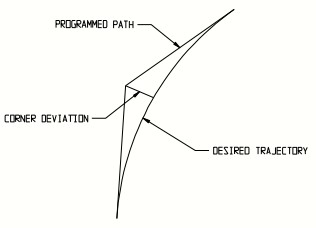
Max Corner Deviation This number sets a default value for the maximum deviation allowed
on a corner. A value of .002 means the control generates a desired path within. .002” of the
programmed path.
Tool Setter: Set if machine has a tool setter.
Tri-Color Cycle Light: Yes if it has the 3 color (Red, Yellow and Green) Cycle Light.
End-of-Cycle Output # The end of cycle light output #. Zero if it doesn’t have an end of
cycle light.
****Software Options****
Allow Modal Restart Enables the ability to start programs from a specific block in the
block. The block is selected using the program editor. It also allows the ability to pick up
on modes, before the selected block, such as federates, spindle commands, tool#s,
cutter comp, etc.
Look Ahead Blocks The maximum number of blocks the control is allowed to look
ahead. The 9000 Series CNC uses an adaptive lookahead algorithm. It looks no further
ahead than it has to. 99.99% of applications require nowhere near the max number of
Look Ahead Blocks. Dependent on processor capacity. Setting is 80 on Series 9000
CNC’s in late 2017.
Look Scope Blocks Generally set to zero.
Transition Radius: A first cousin to the earlier parameter Max Corner Deviation,
defining how closely the desired path follows the programmed path at corners. A lower value
creates a desired path closer to the programmed path. A higher value permits smoothing
the corner, reducing cycle time. This default value is used if there is no G187, G188 or G189
command in the program. Usually .020.
Small Move Multiplier Allows higher speeds in tiny line segments, producing faster and
smoother overall performance. A good value is 8.
Max solid graph file size: The high limit for a solid model graphics file. Dependent on
processor capacity and graphics chipset. Usually 30,000.
Special Flags: Normally set to 0
Bit 2 (#2) will shut off trig help.
Bit 3 (#4) will shut off cutter compensation.
Note: Trig Help is cnc background functionality that finds arc endpoints and tangents in
conversational programs. The output from some CAD⁄CAM systems plays poorly with
Trig Help. If this interference occurs, usually shown by a huge arc in the toolpath when
it should be a small arc, machine performance is corrected by turning Trig Help off.
Setting Misc parameter Special Flags to 2 (turning off Trig Help) does not help the situation,
because the setting does not persist. There are certain Prog-Run defaults invoked by the
CNC when any program is run. One of them is to enable Trig Help.
A workaround for this circumstance is to insert a line “PB81 = 2” near the top of any CAD⁄CAM
text program. A CAD⁄CAM post processor can usually be edited to add this line automatically.
Another workaround is to set PB208 = 0 in MDI. If PB208 equals 0, then Trig Help is not
turned on as a Prog-Run default and thus the setting in Misc parameters Special Flags does
persist. The value in PB208 persists through power cycles, i.e. when PB208 has been set to
zero and Special Flags = 2, then Trig Help is turned off and remains off.
Tool Setting: If set to Current Tool when setting tool lengths, the control assumes that the
active tool # is the tool length that is being set. If set to “Any Tool” the control will prompt the
operator for the tool #.
Tool Setting, Using Work Offsets If set to Yes, the work offsets are used when setting
the tool length. The option is for those that touch tools off on the table or setting guage.
G5#-Z on Tool #1 Only Used to specify tool #1 as the master tool.
SingleBlock thru CannedCycles and TC’s If set to Yes, (and in single block) tool changes,
drill cycles and canned cycles are executed with 1 cycle start. If set to No each block of the
tool changes, drill cycles or canned cycle requires a cycle start.
CPU Warning Temperature In Centigrade. Used to check for CPU overtemp.
CPU Warning Temperature If set to a non-zero value and the value is exceeded a message
WARNING: CPU is dangerously warm. To avoid abrupt shutdown, shutdown the machine as soon
as possible. Press<ESC> to clear this message.
****Post M codes table****
Post M code #0 M codes listed here will be executed after all other operations within the block.
Post M code #1
Post M code #2
Post M code #3
Post M code #4
Post M code #5
Post M code #6
Post M code #7
Post M code #8
Post M code #9
****Spindle Power Monitoring****
Spindle Power Raw Value read from ADC, 0 to 255
Spindle Power Scale Multiplier to obtain Spindle Power Value
Spindle Power Value (Amps) Calculated from the spindle power raw and scale
****Manual Threading****
1 st Depth First cut amount for manual mode threading.
Minimum Cut Minimum cut amount for manual mode threading.
Finish Passes # of finish passes for manual mode threading.
European Code Parameter and Operation Descriptions
European Code Limits axis and spindle motion as described below
Feedhold Input The input for signaling feedhold to the cnc. Depending on machine safety
requirements, the door switch or light curtain signal usually goes to the feedhold input.
Setup Button The feedhold override button, a hold-to-run switch in some European code
scenarios.
When European Code is set to Yes, the cnc software limits machine behavior to comply with
European Union safety regulations. Below is a description of how the software operates.
If the door open switch is wired to the feedhold input and European Code = No: When
the door opens, it shuts the spindle off and feedholds the machine. When the door is open,
the spindle will not start. When the door is open, the machine will not do an MDI move, will not jog,
and will not do a move in run mode; however, it will handwheel.
The machine will do I⁄O related functions other than turning on the spindle (i.e. arm-in, drawbar, etc.)
If the machine is tapping and the doors open, the machine will finish the tap, feedhold, and stop the
spindle.
If the doors are opened while the machine is running:
1. The spindle will shut off.
2. The axis will stop moving.
3. The feedhold light will come on.
4. The spindle will not restart.
To continue operation:
1. Close the doors (Cycle Start will flash).
2. Push the CW button on the front panel (the spindle will restart).
3. Push the Cycle Start Button on the front panel (Cycle Start will stop flashing and the
Feedhold light will go out).
If the machine is not running and the spindle is not running, opening the doors should have no
effect on the machine. However, the Feedhold light will come on.
If the door open switch is wired to the feedhold input and European Code = Yes When the door
opens, which is allowed by pressing the door open button, the spindle shuts off as well as
feedholds the machine. When the door is open, the spindle will not start. When the door is open,
the machine will not do an MDI command; it will not jog nor will it start running a program. It will not
handwheel. If the machine is tapping and the doors open, the machine will finish the tap and then
feedhold and stop the spindle.
If the door is open, the machine will allow the tool changer to index only one position at a time using
the tool changer utility or the tool setting utility.
If the door is open and Setup is held in, the machine will jog up to 60 ipm.
If the door is open and Setup is held in, the machine will handwheel up to the 50% rate on the
feedrate override switch, which is .1mm per click of the handwheel. (It is difficult to generate
speeds greater than 1000 mmpm in this mode). Modifying the distance per click of the handwheel
also requires a password available only to the machine builder.
If the doors are opened while the machine is running:
1. The spindle will shut off.
2. The axis will stop moving.
3. The feed-hold light will come on.
4. The spindle will not restart.
If Setup is pressed, the machine will move at the clamped feedrate while the button is held in.
To continue operation:
1. Close the doors (the Cycle Start Button will flash).
2. Push the CW button on the front panel (the spindle will restart).
3. Push the Cycle Start Button on the front panel (the Cycle Start Button will stop flashing and
the feedhold light will go out).